The Red Spider Canyon layout - Page 5 of 6


The entire operation of the layout is made possible by using an Arduino Mega 2560 board placed, like all the other components, under in the lower part of the layout.
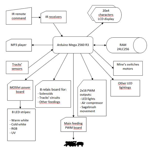
In particular, the entire system is depicted in the diagram to the right, where you can see the main devices used for the complete management of switches, track circuits, lightings, sound effects, etc. Everything is handled with an infrared remote command and the operator can command all the functions using two LCD panels.
Obviously, all the programming of the microprocessor, written with the Arduino IDE software, is entirely specifically written by me, with the exception of some libraries for a couple of specific boards. It should be cleared that, however, the high integration of so many devices, with their libraries and the significant amount of required code, often leads to incompatibilities between hardware and software components. Even in my case, in fact, during the integration of hardware and software, I had to deal with some conflicts due to simultaneous use of the resources of the Arduino board itself and this led, with great expenditure of time, to the identification of the problems and then to subsequent needed corrections to wirings and to portions of the libraries and code.
Another problem I had to deal with, was the interferences due to the electrical switches' solenoids' magnetization current, given that the proximity of the conductors (located in such a small place) caused strong disturbances to the microprocessor's operation, distorting the readings coming from train presence's sensors. The result was that, by moving switches, there were mistakenly train detections (the so-called false positives), with the obvious problems of a general malfunction. I was therefore forced to partially rewire the system, using shielded cables (with ground connection) for all cables connecting solenoids and the main power feeder. Next time I won't make the same error again!


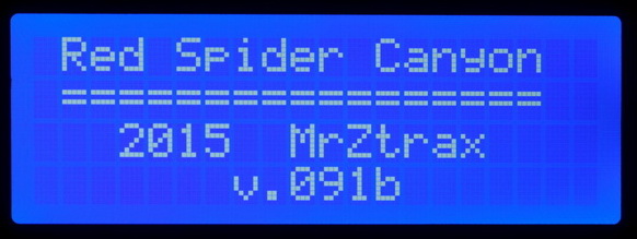
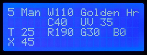
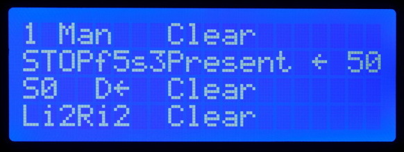
The GUI interface between the system and the operator is made up by two LCD displays connected in parallel on the same I2C bus line, so they can show the same informations, but placed on two different sides of the layout, for a better operability of the system. They can show a large amount of informations and, above all, could be used to set multiple parameters, allowing the operator to intervene on every little aspect of the system without having to re-program the microprocessor by scratch.


