Techniques and Z scale mainteinance
Semaphores 89401 / 89402 / 89403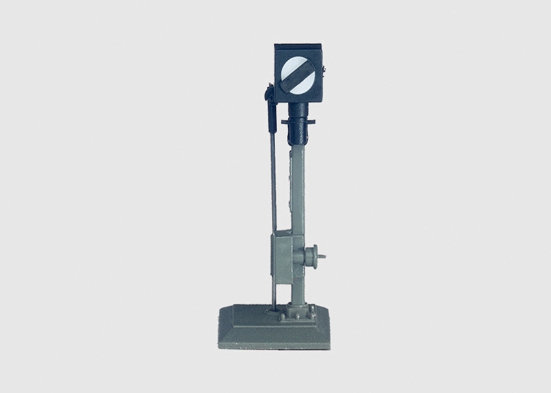
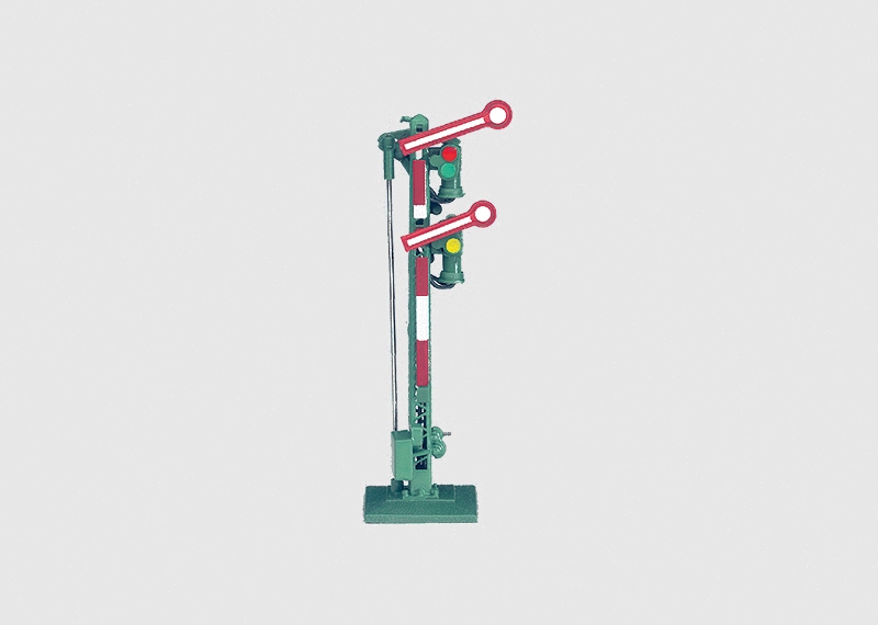
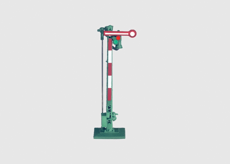
Articles 89401, 89402 and 89403 are interesting mobile signals produced by Märklin since 2003. Before then, there were only the light signal 8939 and the single-arm 8940 semaphore, this featured by its motor in the horizontal position, aesthetically not so realistic. With the introduction of new articles, Märklin's offered art. n.89391, 89392 and 89393 light signals and new arm-semaphores 89401 and 89402 were introduced, in addition to the new 89403 maneuver signal. In these 3 latter articles, the motor was placed under the same traffic light, in a vertical position. The advantage of having the engine in such a hidden position meant that it had to be a considerable space below the support plane, requiring a clearance of about 65mm, not so easy to achieve.
The instruction manual of these articles is here.
All these three products, while being well-constructed, have common mandatory microscopic components, with connections for LED lighting (2 wires: yellow and brown) for motor control (3 wires: yellow for the common and two blue ones to change the semaphore appearance), for switching on/off the break track circuit (2 red wires).
Unfortunately, in a couple of cases, movement (controlled by 16Vac solenoids) sometimes jammed, extremely unpleasant situation when your device is already mounted in the plastic, moreover in a position not easy to reach.
Problem arise from the fact that the two control circuits have a common safety limit switch on their common contact (yellow wire) that, in addition to the fact that such a small size mechanics sometimes can oppose a certain effort to maneuver, makes the semaphore not comlpetely to move, thus being stucked in an intermediate position without further possibility of movement.
Possible solution involves opening the engine casing and performing a small soldering to eliminate this safety contact. To do this you need to have a 2mm cut screwdriver, tweezers, tin, and a very fine tip solderer.
Then you need a lot of patience, otherwise we will eventually ruin your precious semaphore.
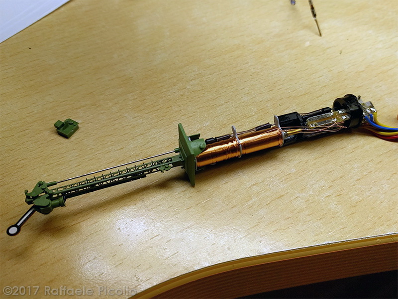
It begins by opening the two shells that enclose the motor, starting from the one that has only a green pin, below the base of the semaphore. Using the screwdriver you have to lever at the bottom, where there are two folded metal fins. Open from below, gently lifting the first half-shell until it is released from its seat at the green pin.
Once the first half-shell has been removed, you must now do the same maneuver with the other half-shell. Be careful that by removing these two protections, the internal mechanism will be very vulnerable, so you must always be very careful and make every move very slowly.
At this point, you just have to remove the black plastic cover that hides the board on which the solenoids' wires are soldered, gently lifting it from the base of the semaphore and pulling. The semaphore should look like in the picture here.
With the semaphore as in the picture, now you can solder the two thin wires on your left together (as shown in the last photo), be careful to achieve a soldering as flat as possible, as to prevent something from touching the plastic protection once shells are closed. This soldering is intended to prevent the solenoid circuit from opening when it reaches the end of the stroke, effectively improving the maneuvering performance. By contrast, this limit switch, designed to protect the solenoids, will be lost, so current will continue to flow as long as the circuit will be held closed. From now on, you must be careful not to close the control contacts for too long, as to prevent solenoids from burning.
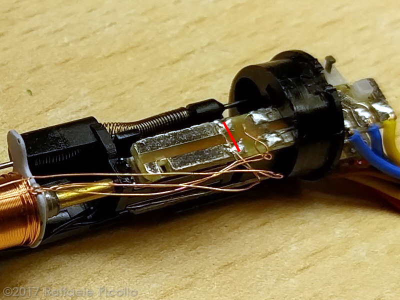
After having placed a drop of silicone oil on the solenoid post and tested its operation, put the plastic cap back into place, first by pushing the pin on the right and then putting it back in place by sliding the solenoid supports in its slots, so place the half-shell with the two pins (eventually place the two pins firmply in place using the tweezers) and finally fix the other half-shell.
Since motion problems arise precisely from the presence of sliding contacts that run the limit switch on the one hand and on the other hand interrupt the power of the track circuit where we want to stop the train, a further improvement could be to eliminate the those contacts by bending their blades using tweezers, before closing the two shells. I suggest bending them rather than eliminating them, as they act as a guide to the movement of the mechanism that, without these blades, could cause problems: better flatten the contacts as much as not to make resistance to movement. In this way, of course, the two red wires will be lost, but the semaphore's mechanism will be even more fluid.
Finally, I recommend that you should operate only if you are expert enough, as the slightest error could lead to irreperable damage to your semaphore.


